
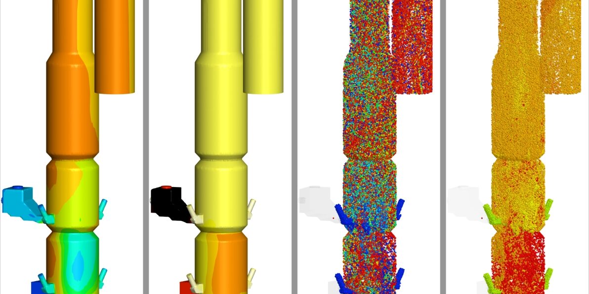
Introduction
Cement manufacturing has evolved from small, energy-intensive kiln systems to highly integrated preheater–precalciner processes designed to improve heat recovery, reduce specific fuel consumption, increase production capacity, and enable greater use of alternative fuels. Despite these advances, cement production remains an energy- and carbon-intensive industry. Calcination alone accounts for about 5% of global fossil CO₂ emissions (Andrew, 2019), while calcination and fuel combustion together account for about 7–8% of global CO₂ emissions (IPCC, 2014). Increasing the use of alternative fuels while maintaining stable calciner operation, raw-material conversion, and emissions performance is therefore an important component of ongoing efforts to improve the sustainability of cement production and reduce global emissions.
The calciner plays a central role in modern cement pyro-processing. Preheated raw meal from the preheater-stage cyclone system enters the calciner, where fuel combustion provides the heat required for limestone decomposition according to the principal endothermic calcination reaction, CaCO₃ → CaO + CO₂. Typically, approximately 90–95% of the raw material is calcined before entering the rotary kiln. Kiln exhaust gas enters through the lower portion of the calciner, while preheated tertiary air provides the primary oxygen for combustion. The high temperatures, intense gas–solid mixing, and available particle residence time make the calciner particularly well suited for co-processing alternative fuels and waste-derived materials.
Municipal sludge waste is one such alternative fuel used in the calciner. Using it in cement manufacturing offers the potential to use a waste stream beneficially while partially reducing demand for conventional fossil fuels. However, municipal sludge waste differs substantially from pulverized coal because of its relatively high moisture content, volatile fraction, ash content, particle characteristics, and fuel-bound nitrogen. These properties introduce additional drying, devolatilization, char oxidation, and emissions-related processes that must occur alongside coal combustion and raw-meal calcination. In particular, the energy required to heat and evaporate sludge moisture can influence local temperatures and reaction rates, while the subsequent release and combustion of volatile species and oxidation of the remaining char can affect oxygen availability, fuel burnout, calcination, and emissions.
Figure 1 presents a simplified schematic of a cement calciner operating with municipal sludge co-firing, together with representative Barracuda predictions that provide an early view of the model outputs discussed later in the post. The schematic highlights the principal material and gas streams relevant to this model extension, including municipal sludge, coal, preheated raw meal, preheated tertiary air, kiln exhaust gas, and the connection between the calciner and the preheater-stage cyclone system. The accompanying contour plots illustrate representative predictions of CO₂ concentration, gas temperature, degree of calcination, and raw-material temperature within the calciner.
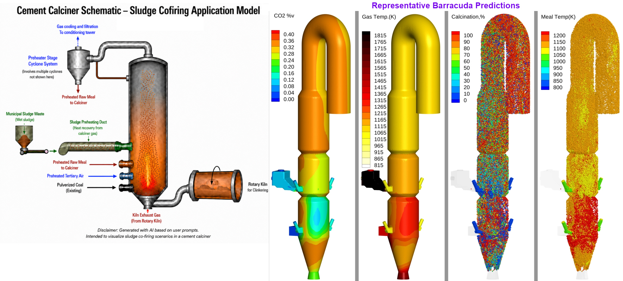
Figure 1. Simplified schematic of the cement calciner sludge co-firing configuration and representative Barracuda predictions of CO₂ concentration, gas temperature, degree of calcination, and raw-material temperature
This work extends CPFD Software’s existing coal-only Cement Calciner Application model, developed using Barracuda Virtual Reactor, to include municipal sludge co-firing. The coal-fired application model represents an industrial-scale cement calciner and incorporates coupled gas-solid hydrodynamics, heat transfer, coal devolatilization and combustion, fuel-based N chemistry, and limestone calcination required to simulate an industrial calciner operation. The coal-only application model was previously validated against available cement-plant data, including outlet gas temperature and raw-meal calcination, and therefore provides the established baseline for the present extension.
The municipal sludge-cofiring model retains the principal geometry, boundary-condition framework, process inputs, heat-transfer treatment, coal combustion chemistry, calcination kinetics, and numerical methodology of the existing coal-only model. The extension introduces the additional model components required to represent municipal sludge waste, including a dedicated sludge feed and composition, sludge moisture evaporation, sludge devolatilization, combustion of sludge-derived volatile species, and oxidation of the remaining sludge char. In the remainder of this application model, municipal sludge waste is hereafter referred to as sludge for brevity. Coal and Sludge are represented separately, allowing their conversion behavior to be evaluated independently while simultaneously resolving their coupled interaction with the gas phase and raw meal. This application model extension demonstrates how Barracuda Virtual Reactor can simulate sludge co-firing in an industrial cement calciner and provides a starting framework for users to develop and evaluate similar alternative-fuel applications using Barracuda. The model focuses on sludge drying, devolatilization, char burnout, coal combustion, raw-meal calcination, gas composition, temperature distribution, and emissions.
The resulting model can also serve as a starting framework for investigating the effects of sludge properties such as composition, particle size distribution (PSD), and location; feed conditions; substitution level; and operating conditions on overall calciner performance. For details of the underlying calciner geometry, process operating conditions and boundary inputs, material definitions, multiphase-flow and heat-transfer treatment, coal combustion and calcination reaction-kinetics framework, and the associated model-setup and post-processing workflow, readers are referred to the original Cement Calciner Application Model.
The present application model extension focuses primarily on the additional model components and considerations required to model sludge co-firing in a cement calciner. CPFD uses information from the literature to develop the application model but does not independently verify its accuracy.
Model Description
The sludge co-firing model builds on the established coal-only calciner configuration by incorporating the additional geometry, material definitions, boundary conditions, and reaction pathways required to represent sludge co-firing. The sludge-specific model inputs and parameters are also primarily derived from Zhu et al. (2024).
Geometry
The baseline calciner geometry is retained from the coal-only application model. The computational domain includes the calciner and its associated connections for kiln exhaust gas, preheated tertiary air, pulverized coal, preheated raw meal, and the calciner outlet. The principal geometric modification is the addition of the sludge preheating and feed duct through which sludge is introduced into the calciner.
Figure 2 shows the computational geometry of the sludge co-firing model and identifies the principal gas and particle-feed locations. Further details of the baseline calciner geometry are provided in the original Cement Calciner Application Model.
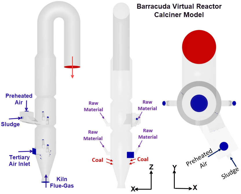
Figure 2: Barracuda Sludge Co-firing Model Schematic
Boundary Conditions and Process Inputs
The sludge co-firing model retains the boundary-condition framework established for the coal-only application model, including the kiln exhaust gas, tertiary air, pulverized-coal and raw-meal feeds, calciner outlet, and wall conditions. The extension introduces a dedicated sludge-feed boundary condition through the added preheating/feed duct, together with the corresponding sludge mass flow, particle properties, and inlet conditions. The 10% and 20% sludge substitution cases are defined on a fuel mass basis, with sludge accounting for 10% and 20%, respectively, of the combined coal and sludge fuel mass flow.
The baseline calciner operating conditions are retained where applicable, while sludge-specific process inputs and any required adjustments to the air distribution are incorporated to accommodate the additional fuel stream. In particular, the total combustion-air supply is maintained, while the distribution between the relevant air streams can be adjusted to support sludge drying, devolatilization, and combustion without altering the calciner’s overall operating basis.
The original Cement Calciner Application Model provides detailed descriptions of the baseline boundary conditions and process inputs. This application model extension describes the sludge-specific feed conditions and operating modifications below.
Feeds and Particle Materials
The model includes three principal particle feeds: raw meal, pulverized coal, and sludge. The raw-meal and coal definitions are retained from the coal-only application model, while sludge is introduced as a separate particle material. This independent representation enables separate evaluation of sludge transport, temperature evolution, drying, and conversion from those of coal and raw meal.
The as-received sludge contains 45 wt% moisture, together with volatile matter, fixed carbon, and ash. These constituents are represented explicitly within the sludge particle definition to capture the sequence of heating, moisture evaporation, devolatilization, and char conversion that occurs after injection into the calciner. The inert ash fraction remains associated with the residual particle as the combustible components are consumed.
The sludge material definition is derived from the available proximate and ultimate analyses and is formulated to provide the particle-phase species required by the Barracuda reaction framework.
Physical Framework
The sludge co-firing model retains the CPFD gas–particle hydrodynamic framework established for the coal-only application model. Sludge is introduced as an additional discrete particle phase and interacts with the gas phase through the same momentum-coupling treatment applied to the other particle materials.
The existing heat-transfer framework is also retained, including gas–particle convection, particle-to-particle conduction, radiation, and wall heat transfer. Sludge participates in the same heat-transfer mechanisms, but requires additional energy to heat the wet particles, evaporate the contained moisture, and support the subsequent conversion of the combustible fraction.
Table 1 summarizes the principal model components retained from the coal-only application model and the modifications introduced for sludge co-firing.
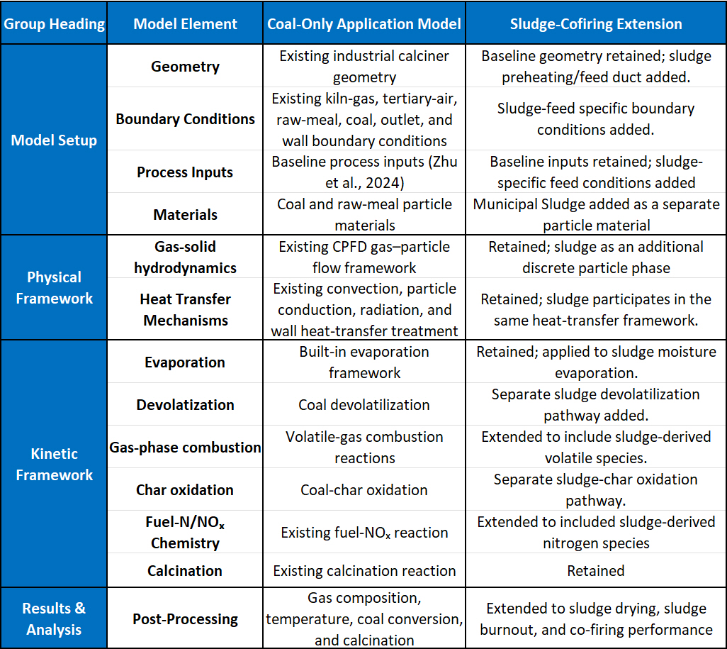
Table 1: Summary of model components retained from the coal-only application model and modifications introduced for the sludge co-firing extension
Model Definition
The sludge co-firing application model retains the compressible, thermally reacting formulation of the coal-only calciner model. Flow boundaries (Flow BCs) are defined for the gas and particle inlets, with the required inputs for mass flow rate, temperature, gas or particle composition, and particle-size distribution, where applicable. In addition to the existing kiln exhaust gas, tertiary air, coal, and raw-meal boundaries, a dedicated Flow BC is defined for the sludge feed through the added preheating/feed duct.
A pressure boundary is retained at the calciner outlet to allow gas and entrained solids to exit the computational domain. The existing thermal-wall treatment is also retained to account for heat transfer through the calciner walls using the specified wall emissivity and thermal resistance.
Raw meal, pulverized coal, and sludge are represented as separate particle materials with their respective particle-size distributions and compositions. The raw-meal and coal definitions are retained from the original application model, while sludge is added as a material containing moisture, volatile matter, fixed carbon, and ash. The sludge composition is derived from its proximate and ultimate analyses and is further described in the sludge material-definition section.
The domain initialization used in the coal-only application model is retained for the sludge co-firing extension. The established Barracuda framework models heat transfer by gas–particle convection, particle-to-particle conduction, and radiation. The same fluid–particle drag treatment is also retained, with the Beetstra drag model applied to momentum exchange between the gas phase and the particle materials.
Figure 3 illustrates the principal Barracuda inputs used to define the gas and particle Flow BCs for the sludge co-firing application model.
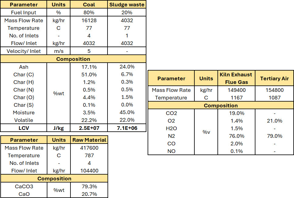
Figure 3: Barracuda Virtual Reactor Sludge Co-firing Model Flow Inputs
A uniform spherical sludge particle diameter of 1 mm is assumed, consistent with the particle size reported in Zhu et al. (2024).
The provided project file and supporting files are intended as a reference modeling framework for Barracuda Virtual Reactor users. They illustrate an approach for modeling industrial equipment such as cement calciners, and users should adjust/modify the provided reaction kinetics, model configuration, equipment geometry, operating conditions, and process inputs to represent their specific application.
Reaction Kinetics
The reaction-kinetics framework established in the coal-only application model is retained and extended to account for the additional conversion associated with sludge waste. The existing framework includes fuel devolatilization, volatile-gas oxidation, char oxidation, fuel-N/NOₓ chemistry, and limestone calcination. For the sludge co-firing application model, additional species and discrete reactions represent sludge devolatilization and sludge-char oxidation while retaining the existing gas-phase combustion, fuel-N/NOₓ, and calcination pathways.
Figure 4 provides an overview of the fuel-conversion and reaction-kinetics framework used in the sludge co-firing application model. Fuel moisture is first removed through evaporation, after which the combustible fraction undergoes devolatilization using a lumped-release approach. The Volatile Estimation Template determines the volatile-gas composition, char composition, and associated thermodynamic properties using user-defined assumptions based on fuel type and composition. The released volatile species subsequently participate in gas-phase oxidation and fuel-N/NOₓ chemistry, while the remaining char undergoes heterogeneous oxidation. Heat released through these combustion pathways establishes the local thermal and reaction environment required to support the endothermic calcination of the raw meal.
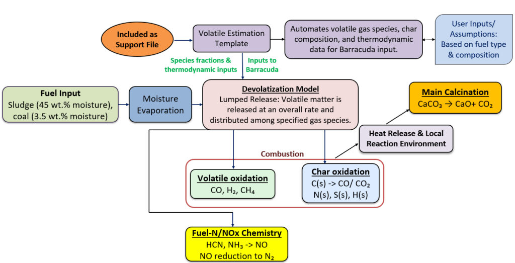
Figure 4. Overview of the fuel-conversion and reaction-kinetics framework used in the sludge co-firing application model.
Moisture Evaporation
The as-received sludge contains 45 wt.% moisture, represented as liquid water within the sludge particle material. Barracuda models moisture evaporation using its built-in evaporation framework. Sensible heating and latent heat associated with moisture evaporation are coupled to the particle- and gas-phase energy balances, allowing the thermal effect of sludge drying to be resolved directly within the decomposition furnace.
The existing Barracuda evaporation framework is applied to the comparatively high moisture loading associated with the sludge feed. The resulting thermal demand influences the subsequent heating, devolatilization, and conversion of the sludge particles.
Volatile Estimate Utility
The Volatile Estimate Utility is provided as part of the application-model support files to help users translate fuel characterization data into the species and thermodynamic inputs required by Barracuda. Using the fuel proximate and ultimate analyses, along with user-defined assumptions for the distribution of constituent elements, the utility estimates both the volatile-gas composition released during devolatilization and the composition of the residual char.
In addition to determining the mass fractions of the volatile gaseous species, the utility determines the residual char composition based on the supplied fuel analysis and the assumed distribution of elements between the volatile and solid phases. The calculation maintains elemental balance between the original fuel, the released volatile gases, and the remaining char.
The utility also provides the thermodynamic quantities required to implement the lumped devolatilization model in Barracuda, including the Heat of Devolatilization and the corresponding Heats of Formation used for the pseudo-volatile species. Together, these calculations provide a consistent mass- and energy-balanced representation of fuel devolatilization.
Users can enter the proximate and ultimate analyses of their own fuels, revise the underlying elemental-distribution assumptions as appropriate to their fuel under consideration, and generate the corresponding volatile-gas fractions, char composition, and thermodynamic inputs for use in Barracuda. The utility therefore provides a practical starting point for extending the application model to other conventional, alternative, or waste-derived fuels.
Sludge Devolatilization
Sludge devolatilization uses the same lumped-model methodology as coal in the original application model, while retaining a separate sludge-specific material and reaction definition. A pseudo-solid species is created within the sludge species to represent the sludge volatile fraction and to track sludge devolatilization independently of coal devolatilization. A discrete devolatilization reaction consumes the corresponding pseudo-solid volatile species and releases the estimated gaseous products into the fluid phase at prescribed mass fractions.
Table 2 summarizes the volatile-gas compositions estimated for coal and sludge using the Volatile Estimate Utility. The sludge volatiles are characterized by a substantially higher CO₂ and HCN fraction and a much lower CO fraction than the coal volatiles. These estimated species distributions are used directly in the respective coal and sludge devolatilization reactions in Barracuda.
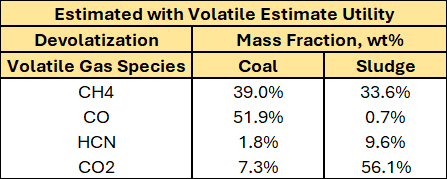
Table 2: Estimated volatile-gas composition for coal and sludge obtained using the Volatile Estimate Utility.
The released CH₄ and CO₂ enter the existing gas-phase combustion framework, while HCN provides the principal sludge-derived nitrogen species entering the fuel-N/NOₓ chemistry. The pseudo-volatile Heat of Formation is defined to preserve both elemental and energy balance during sludge devolatilization.
Sludge-Char Oxidation
Following moisture removal and devolatilization, the remaining carbon-rich fraction of the sludge undergoes heterogeneous char oxidation.
The sludge-char oxidation formulation accounts for both kinetic and mass-transfer limitations on carbon conversion. The oxidation products are partitioned between CO and CO₂ using the same temperature- and oxygen-dependent split-factor approach employed for carbon oxidation in the original application model.
Maintaining separate coal- and sludge-char reaction definitions allows independent quantification of their respective burnout levels while preserving their simultaneous interaction with the local oxygen concentration, temperature field, and gas–particle hydrodynamics.
Integration with the Existing Combustion and Fuel-N/NOₓ Framework
The homogeneous gas-phase combustion and fuel-N/NOₓ mechanisms established for the coal-only application model are retained without modification. Sludge-derived volatile species are introduced directly into this existing reaction network rather than through a separate homogeneous chemistry model.
The combustible sludge-derived species participate in the established oxidation reactions, while HCN and NH₃ enter the existing fuel-N reaction pathways governing NO formation and reduction. Similarly, the existing solid-phase conversion framework is retained for the applicable residual char species.
The complete homogeneous combustion, fuel-N/NOₓ, coal-char oxidation, and associated rate expressions are therefore not repeated in this extension. Readers are referred to the original Cement Calciner Application Model for the full reaction set, rate coefficients, and Barracuda implementation.
Calcination
The limestone-calcination kinetics from the coal-only application model are retained without modification. Consequently, the sludge extension does not alter the intrinsic reaction model for
$$ CaCO_3 \rightarrow CaO + CO_2 $$
Any effect of sludge co-firing on raw-meal calcination therefore arises through changes in the local thermal and reaction environment associated with sludge drying and combustion, including changes in temperature, gas composition, oxygen availability, and the general hydrodynamics within the calciner.
The sludge-specific reaction definitions and user-defined expressions required for devolatilization and char oxidation are included in the Barracuda Project file, which is part of the support file.
Results and Discussion
The sludge co-firing simulation was evaluated using both qualitative flow-field visualization and quantitative post-processing of important dependent variables at the calciner outlet. The results focus on the additional behavior introduced by sludge co-firing, including sludge heating and drying, fuel conversion, raw-meal calcination, temperature distribution, outlet gas composition, and NO emissions. The corresponding coal-only results and validation are documented in the original Cement Calciner Application Model.
Figure 5 compares the baseline coal-only calciner results with the sludge co-firing case for a 20% fuel substitution with municipal sludge. Sludge co-firing reduces the calciner outlet temperature to approximately 1112 K, compared with 1133 K for the coal-only Barracuda case and 1140 K from the plant-data coal-only reference. This reduction mainly comes from the additional thermal demand of heating and drying the wet sludge. Even with this lower outlet temperature, the predicted raw-material calcination remains relatively high at approximately 89%, compared with 93% for the coal-only Barracuda case and 92% for the plant-data reference. The outlet gas composition also shifts in a manner consistent with the altered fuel-conversion behavior: CO₂ decreases from 36.4% to 33.6%, while O₂ increases from 1.7% to 2.9% in the sludge co-firing case, consistent with the lower burnout of sludge-specific carbon char.
These results indicate that introducing wet sludge imposes an additional thermal load on the calciner, lowering the gas temperature and slightly reducing the extent of calcination. At the same time, the model predicts that calcination remains relatively high and that the overall calciner response remains physically consistent, demonstrating that the Barracuda framework can capture the coupled effects of sludge drying, fuel conversion, and raw-meal decomposition within the same industrial calciner environment.
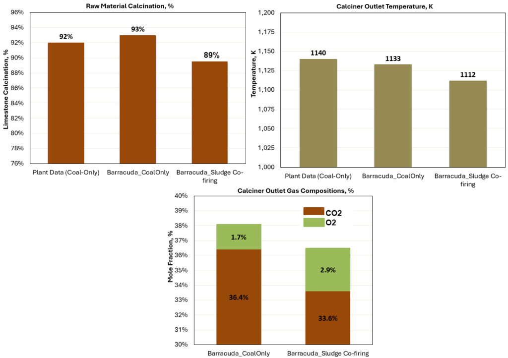
Figure 5: Sludge Co-firing and Coal-only results comparison
The following figures further examine the spatial distributions of temperature, gas composition, particle behavior, and conversion within the calciner to provide additional insight into how sludge co-firing influences the internal process behavior.
Figure 6 shows the comparison of time-averaged gas-temperature and O₂ mole-fraction distributions for the coal-only and 20% sludge co-firing cases predicted by Barracuda. Sludge co-firing noticeably alters the internal thermal and oxygen distributions within the calciner. Compared with the coal-only case, the 20% sludge co-firing case develops a more pronounced high-temperature region near the sludge-side furnace and lower calciner, while the upper calciner remains cooler. The O₂ field also extends farther through the calciner, indicating lower overall oxygen consumption and reduced fuel conversion. These changes reflect the combined effects of sludge heating and drying, altered fuel conversion, and the endothermic calcination process, resulting in a stronger axial temperature gradient and a more spatially distributed combustion environment inside the calciner.
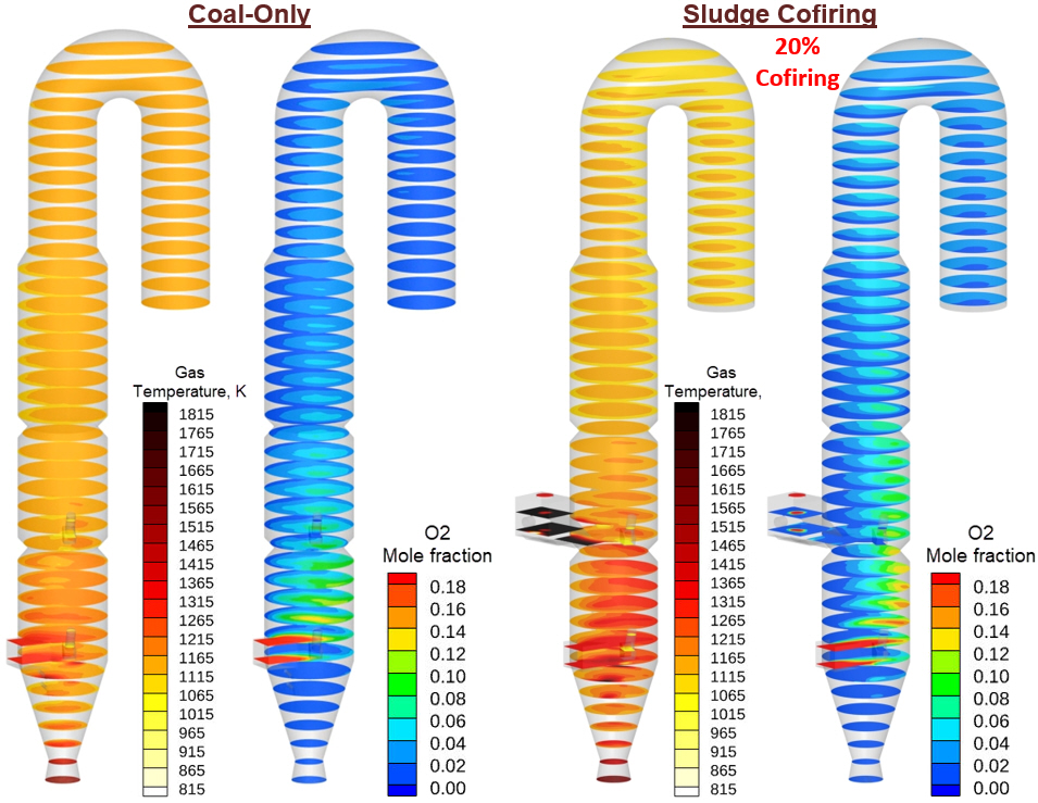
Figure 6. Comparison of time-averaged gas-temperature and O₂ mole-fraction distributions for the coal-only and 20% sludge co-firing cases.
Figure 7 shows the time-averaged spatial distributions of CO₂ and CO for the coal-only and 20% sludge co-firing cases. CO is concentrated primarily in the lower calciner and near the fuel-injection regions, where devolatilization and char oxidation are most active, and decreases farther downstream. Sludge co-firing changes the location and extent of these localized CO-rich regions, indicating a redistribution of fuel conversion within the calciner. CO₂ remains the dominant carbon-containing product through most of the calciner and provides a complementary indication of combustion progression and raw-meal calcination. Together with the O₂ and temperature fields discussed previously, these contours show that sludge addition modifies the spatial distribution of reaction activity rather than producing a uniform change throughout the calciner.
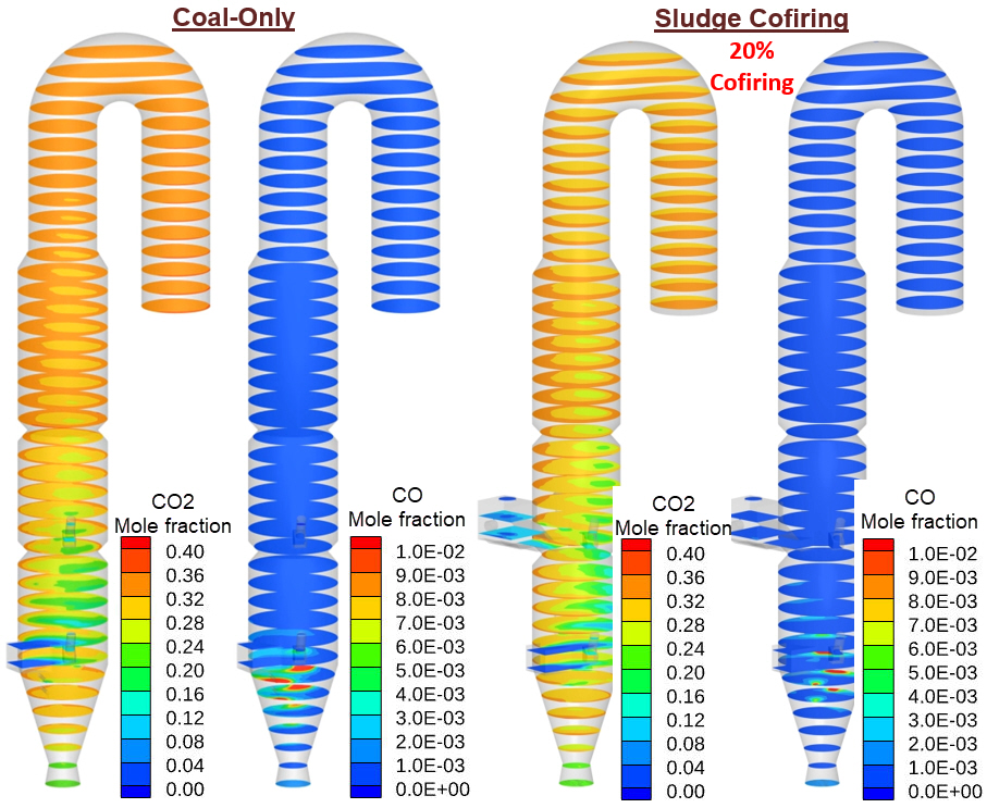
Figure 7. Comparison of time-averaged CO₂ and CO mole-fraction distributions for the coal-only and 20% sludge co-firing cases.
The sludge-conversion animation tracks the degree of drying, degree of devolatilization, and sludge char-carbon burnout throughout the 20% sludge co-firing case.
The degree of drying increases rapidly as the initially wet sludge particles are heated, with moisture removal occurring early in the particle trajectory. The degree of devolatilization subsequently increases as the dried particles continue to heat and release volatile matter into the gas phase. Presenting these quantities on a 0–100% basis directly visualizes where drying and devolatilization occur within the calciner and how these processes evolve with particle residence time and temperature. The animation also shows that drying and devolatilization are distinct stages of the sludge conversion process. Rapid drying does not imply complete fuel conversion; after moisture removal and volatile release, the remaining solid carbon must still undergo heterogeneous char oxidation in the calciner, which is strongly influenced by local conditions.
Figure 8. Evolution of sludge drying, devolatilization, and char-carbon burnout during particle transport through the calciner for the 20% sludge co-firing case.
Figure 9 shows the mass-weighted residence time distribution (RTD) at the calciner outlet, evaluated for the raw material, coal, and sludge particles in the 20% sludge co-firing case. The cumulative and normalized RTD curves show clear differences in the transport behavior of the three particle feeds.
The coal particles exhibit the shortest residence times, with D10, D50, and D90 values of 6.0, 9.8, and 19.2 s, respectively. The raw-material particles show intermediate residence times of 7.2, 11.9, and 26.9 s, while the sludge particles remain in the calciner the longest, with corresponding residence times of 12.3, 16.5, and 30.3 s.
The longer sludge residence time provides additional opportunity for particle heating, devolatilization, and char oxidation following injection. However, residence time alone does not determine fuel conversion; sludge burnout also depends on particle size, heat transfer, local oxygen availability, reaction kinetics, and interactions with the surrounding gas and other solid phases. The RTD results therefore provide useful transport context for interpreting the drying, devolatilization, and burnout behavior observed elsewhere in the model.
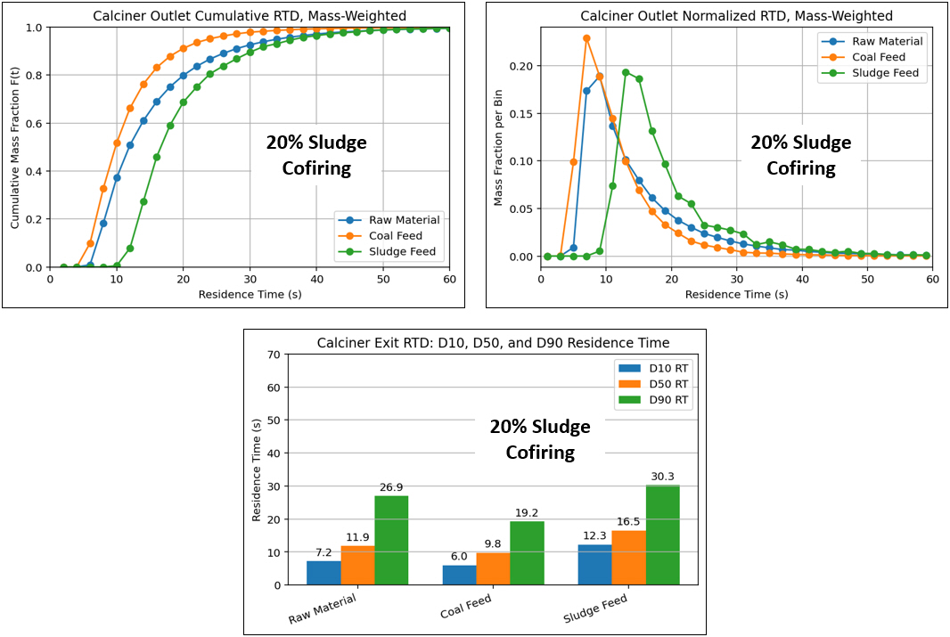
Figure 9: Mass-weighted calciner-outlet residence time distributions for raw material, coal, and sludge particles in the 20% sludge co-firing case. Cumulative and normalized RTD curves are shown together with the corresponding D10, D50, and D90 residence times.
The animation in Figure 10 illustrates the calcination behavior of the raw meal in the 20% sludge co-firing case using the local degree of calcination together with the raw-material particle temperature. To make internal particle behavior visible, the animation uses half-section views of the calciner, exposing the reactor interior rather than showing only the external particle field. This allows observation of raw-meal heating and CaCO₃ conversion throughout the calciner.
The displayed degree of calcination is referenced to the raw-meal condition at the calciner inlet. Therefore, the animation does not include any precalcination already present in the incoming raw meal. Incoming raw-meal particles are shown as 0% on the displayed scale, while 100% corresponds to complete conversion of the CaCO₃ remaining at the calciner inlet. The field should therefore be interpreted as the additional calcination achieved within the modeled calciner.
For the 20% sludge co-firing case, the model predicts an overall calcination of 89.4% and a mean raw-material particle temperature of 1104.6 K at the calciner outlet. The animation provides the spatial context for these values by showing where heating and calcination develop within the calciner.
Figure 10. Raw-material particle temperature and degree of calcination during transport through the calciner for the 20% sludge co-firing case.
Figure 11 illustrates the time-averaged spatial distribution of nitrogen oxide (NO) formation by comparing the coal-only baseline with the 20% sludge co-firing case. Cross-sectional slices along the calciner height, together with longitudinal section views, expose the internal gas-phase distribution and show how nitrogen-oxide concentrations evolve from the lower combustion region toward the calciner outlet.
In both cases, concentrations peak primarily in the lower calciner and fuel-combustion region, where fuel conversion and nitrogen release are most intense. As the gas travels upward through the calciner, concentrations generally decrease and become more spatially uniform. The 20% sludge case changes the local distribution within the lower reaction zone, reflecting the additional fuel-bound nitrogen introduced with the sludge and its interaction with the local combustion environment. Downstream concentrations are governed not only by the initial formation of nitrogen oxides, but also by subsequent transport and reduction reactions as the gas passes through the calciner.
The comparison therefore provides spatial context for the outlet emissions results and shows that the influence of sludge co-firing on nitrogen-oxide emissions depends on the combined effects of fuel-N release, local temperature, oxygen availability, and subsequent NO reduction pathways, rather than on fuel nitrogen content alone.
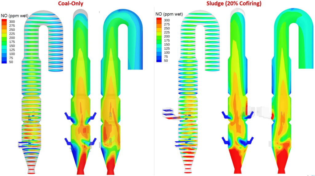
Figure 11: Spatial distribution of nitrogen oxides for the coal-only baseline and 20% sludge co-firing case.
The model provides a flexible framework for evaluating the effects of parameters such as sludge co-firing rate, sludge particle-size distribution, sludge injection location, fuel properties, and air distribution on calciner performance and fuel conversion.
Modeling Instructions
The user is expected to have completed basic Barracuda training: Barracuda Virtual Reactor New User Training | CPFD Software (cpfd-software.com).
- Download the support files provided along with this post.
- Unzip the support file and place it in the new folder created for running this Cement Calciner application model.
- Open a new Barracuda session.
- From the File menu, choose Open Project. Navigate to the working directory and select Calciner_thermal_decomposition_furnace.prj.
- Click on Setup Grid -> 3. Generate Grid.
The project file is already set up with the appropriate inputs and includes the following:
- Grid
- Base Materials.
- Particles.
- Initial Conditions
- Fluid ICs.
- Particle Species.
- Boundary Conditions
- Pressure BC at the Calciner outlet for gas and particle exit.
- Flow BCs for flow inlets.
- Thermal Wall BCs – Account for heat loss through the Calciner walls.
- Heat Transfer
- Particle-to-Particle Heat Conduction
- P-1 Radiation Model
- Chemistry Setup
- Post Processing
- Visualization Data
- Average Data
- Flux Plane
The reaction kinetics for this project, which are already set up under the Chemistry section in the project file, are described below.
Chemistry
The chemistry setup for the sludge co-firing model follows the same Barracuda workflow described in the original Cement Calciner Application Model. The existing reaction framework is retained and extended for the sludge co-firing cases and reactions described in the Reaction Kinetics section.
Readers are referred to the coal-only Cement Calciner Application Model post for detailed instructions on adding and modifying reactions, defining volume-averaged and discrete chemistry, configuring Arrhenius rate coefficients, implementing user-defined rate expressions, and modifying reaction parameters in Barracuda. The accompanying sludge co-firing Barracuda Project file (available in the Download package) contains the complete chemistry setup for this extension and can serve as a starting point for further modifications or for incorporating other fuels.
Time Controls
- Enter 0.0005 seconds for the Time Step and 300 seconds for the End Time.
- Set the Restart Interval to 100 seconds.
For all other model-setup and implementation steps not specifically addressed in this extension, refer to the coal-only Cement Calciner Application Model post.
Run
- Click on Run and then click on Run Solver.
- Select GPU Parallel if you have the required GPU parallel license.
Post-Processing Results
With Tecplot
The Tecplot post-processing workflow used for the sludge co-firing extension follows the same procedure established for the coal-only Cement Calciner Application Model. Readers are referred to the original application-model post for detailed, step-by-step instructions for generating gas-phase contour plots, particle/solids profiles, animations, applying value blanking, loading equation files, and creating reusable Tecplot style (.sty) files. Users unfamiliar with Tecplot should also review the Getting Started With Tecplot For Barracuda® training material before post-processing.
The same workflow applies to the sludge co-firing case, with the plotted variables modified as needed to examine sludge-specific quantities such as particle distribution, temperature, moisture removal, devolatilization, char burnout, and calcination. Equation (.eqn) files are provided with this extension to generate the custom variables used in the results, including Degree of Sludge Drying, Degree of Sludge Devolatilization, Sludge Char-Carbon Burnout, Degree of Calcination, and NO concentration (ppm). Tecplot style (.sty) files are also provided to reproduce the corresponding contour plots and animations presented in this post.
Before applying the supplied Tecplot style files, load all required Barracuda result files, including the complete time series where applicable. Then evaluate the provided equation (.eqn) files across all loaded results so the derived variables are available at every relevant time step. Once these variables are computed, use the following procedures to reproduce the figures and animations presented in this post.
Figure 6: Time-Averaged Temperature and O₂ Comparison
To reproduce the four-panel time-averaged temperature and O₂ comparison shown in Figure 6:
- Navigate to Post-Run in the Barracuda project tree and select either View Results or Launch Tecplot.
- Load the appropriate time-averaged Barracuda results into Tecplot.
- Create four frames and arrange them side by side to form a four-panel view.
- Right-click the first frame, select Load Frame Style…, navigate to the unzipped support-file directory, and load Figure6_Temperature_Coal.sty.
- Repeat the same procedure for the remaining three frames using Figure6_O2_Coal.sty, Figure6_Temperature_SludgeCofiring20pct.sty, and Figure6_O2_SludgeCofiring20pct.sty.
- Arrange and size the four frames as required to reproduce the comparison shown in Figure 6.
Follow the same general procedure with the other supplied Tecplot-style files to reproduce the corresponding static figures in the post.
Figure 10: Calcination and Raw-Material Temperature Animation
To reproduce the four-panel animation shown in Figure 10:
- Load the complete time series of Barracuda results into Tecplot.
- Compute Degree of Calcination across all loaded time steps by selecting Alter → Data → Specify Equations and loading Figure10_DegreeOfCalcination.eqn.
- After the variable has been computed for the complete time series, apply blanking to isolate the first half-section of the calciner.
- Right-click the frame, select Load Frame Style…, and load Figure10_DegreeOfCalcination_FirstHalfSection.sty.
- Copy this frame, modify the blanking in the copied frame to isolate the second half-section of the calciner, and load Figure10_DegreeOfCalcination_SecondHalfSection.sty.
- Copy the frame two additional times and arrange all four frames side by side.
- Configure the third frame to display the first half-section of the raw-material temperature field and load Figure10_RawMaterialTemperature_FirstHalfSection.sty.
- Configure the fourth frame to display the second half-section and load Figure10_RawMaterialTemperature_SecondHalfSection.sty.
- Align and size the four frames to reproduce the layout shown in Figure 10.
- Create the animation across the loaded time series using the standard Tecplot animation procedure described in the original application-model post.
This produces a synchronized four-panel animation showing the Degree of Calcination and raw-material temperature in the first and second half-sections of the calciner.
You can follow the same general procedure for the other supplied equation and style files. First, compute the required derived variables across all applicable loaded results using the corresponding .eqn files, then apply the provided .sty files to reproduce the figures and animations included with this application model extension.
This concludes the Cement Calciner Application Model Extension – Sludge Co-Firing, demonstrating sludge co-firing within the calciner thermal decomposition furnace.
References
Andrew, R. M. (2019). Global CO₂ emissions from cement production, 1928–2018. Earth System Science Data, 11, 1675–1710. https://doi.org/10.5194/essd-11-1675-2019
IPCC, 2014: Climate Change 2014: Mitigation of Climate Change. Contribution of Working Group III to the Fifth Assessment Report of the Intergovernmental Panel on Climate Change [Edenhofer, O., R. Pichs-Madruga, Y. Sokona, E. Farahani, S. Kadner, K. Seyboth, A. Adler, I. Baum, S. Brunner, P. Eickemeier, B. Kriemann, J. Savolainen, S. Schlömer, C. von Stechow, T. Zwickel and J.C. Minx (eds.)]. Cambridge University Press, Cambridge, United Kingdom, and New York, NY, USA
Zhu, L., Mao, Y., Liu, K., Tong, C., Liu, Q., & Xie, Q. (2024). The Co-Processing Combustion Characteristics of Municipal Sludge within an Industrial Cement Decomposition Furnace via Computational Fluid Dynamics. Mathematics, 12(1), 147.